7 水力计算
7.1 一般规定
7.1.1 管道水力计算应根据给定的管道布置、管径、介质流量及其参数计算管道的压降和通流能力。
7.1.2 计算管道压降应考虑一定的裕量,可取计算压降的5%~10%。
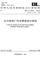
7.1.3 管子摩擦系数可按雷诺数Re及管壁相对粗糙度ε/Di查取(图7.1.3),也可按下列规定确定:
1 雷诺数可按下式计算:

式中:Re——雷诺数;
ω——管内介质流速(m/s);
Di——管子内径(m);
γ——介质运动粘度(m2/s);
μ——介质动力粘度(Pa·s);
ν——介质的比容(m3/kg)。
水和水蒸气粘度值应按本规范附录D的规定选取。
2 管壁相对粗糙度等于管子等值粗糙度ε与管子内径Di之比。在管内介质处于层流状态时,各种管子的等值粗糙度可按本规范附录D的规定选取。
3 管子摩擦系数也可按下列方法计算:
1)当Re小于2320为层流区时,可按下式计算:
2)当Re小于4000且大于2300为层流向紊流过渡的不稳定区域时,可查取管子摩擦系数(图7.1.3)。
3)当Re小于![]() 且大于400为紊流光滑管区时,可按下式计算:
且大于400为紊流光滑管区时,可按下式计算:

4)当Re小于![]() 且大于
且大于![]() 为紊流粗糙管过渡区时,可按下式计算:
为紊流粗糙管过渡区时,可按下式计算:

5)当Re大于![]() 为紊流粗糙管平方阻力区时,可按下式计算:
为紊流粗糙管平方阻力区时,可按下式计算:


图7.1.3 管子摩擦系数
7.1.4 管道总阻力系数应按下式计算。
式中:ξt——管道总阻力系数;
λ——管道摩擦系数;
L——管道总展开长度,包括附件长度(m);
∑ξ1——管道附件的局部阻力系数总和。
管道附件的局部阻力系数可按本规范附录D的规定选取,计算时应根据所用管件的具体情况选用。
7.1.5 管道系统的压力损失应包括直管的沿程阻力损失和管道组成件的局部阻力损失。对于管道的压力损失,应计及终端和始端的高度差引起的压力损失,并应符合下列规定:
1 在两条阻力不同而管径相同的并联管道中,介质流量的分配应按下式进行计算:

2 对于并联管道(图7.1.5-1),已知总流量qv,求各分管道中的流量可采取下列方法进行计算:

图7.1.5-1 并联管道
1)根据管径、长度和管道粗糙度假设通过管路1的流量![]() ;
;
2)由![]() 求出管路1的损失
求出管路1的损失![]() ;
;
3)由![]() 求通过管路2及管路3的流量
求通过管路2及管路3的流量![]() 和
和![]() ;
;
4)假设总量流量qv按![]() 与
与![]() 的比例分配给各分管道,则各分管道的计算流量可按下列公式计算:
的比例分配给各分管道,则各分管道的计算流量可按下列公式计算:

5)用计算流量qv1、qv2、qv3求取hf1、hf2、hf3以核对流量分配的正确性。计算结果应使各分管道的损失差别在允许的误差范围内。
3 对于先并联后串联管道(图7.1.5-2)的总阻力系数,应按下式计算:

式中:ξ1~3——1~3段管道总阻力系数;
ξ2~3——2~3段管道总阻力系数;
ξ3——3点处的阻力系数;
ξ3~4——3~4段管道总阻力系数。

图7.1.5-2 并联后串联的管道
4 先串联后并联的管道总阻力系数应按式7.1.5-5计算,其中三通阻力计算与流动方式和支流与主流流量比有关,三通支流侧的阻力系数应按下式计算:

式中:ξb——支流侧的阻力系数;
ξh——主流侧的阻力系数。
5 当管径不同时,应采用式7.1.5-7折算到计算管径Di1下的阻力系数后才可使用式7.1.5-1和式7.1.5-5计算。

7.1.6 管内介质的流速和质量流速应分别按下列公式计算:

式中:![]() ——管内介质的质量流速[kg/(m2·s)]。
——管内介质的质量流速[kg/(m2·s)]。
7.1.7 管内介质的动压力应按下列公式计算:
或
式中:pd——管内介质的动压力(Pa)。